Raktáron


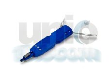
Távközlési réz erű hálózatoknál szigetelet réz ér összekötsére szolgáló szerszám. A fogó alkalmas elágazó és egyenes kötésekhez.
1. INTRODUCTION
Model MR-1 Hand Crimping Tool 251101-1 is designed to crimp PICABOND Connectors in through, tapping, and bridging operations. The tool can be hand-held or it can be used in Tool Holder 251852-1 with or without the Frame Adapter 229175-1.
Read the instructions packaged with these accessories. NOTE All dimensions on this document are in metric units [with U.S. customary units in brackets]. Figures and illustrations are for reference only and are not drawn to scale.
Reasons for reissue of this sheet are provided in Section 11, REVISION SUMMARY.

2. DEblockedION (Figure 1)
The tool features two wire supports, a set of dies (anvils and crimpers), a wire cutter, and a handle assembly.
In use, the wire supports hold and position the wires in the crimpers. As the tool is cycled, the wire cutter cuts off excess wire, then the crimping dies crimp the connector to the wires.
Continuous pressure applied to the moving handle forces the link to snap the tool handles closed, thus completing the crimp cycle. After the cycle is completed, depress the release lever to open the handles and remove the crimped connector.
3. CONNECTOR SELECTION
Determine the wire gage and combination of conductors to be joined. Then refer to Figure 2 for the correct connector. Note the PICABOND connectors can be used for 28 through 19 AWG copper conductors that are insulated with plastic, paper, or pulp materials.
4. PREPARING CABLE
Open and prepare the cable in the usual manner. There is no special procedure required when using the Model MR-1 tool.
5. WIRE PLACEMENT
NOTE The essential difference of the various connections is the placement of the wires in the wire supports. Determine the type of connection to be made, then refer to the applicable Paragraph (5.1, 5.2, or 5.3) and insert the wire accordingly.
5.1. Through Connections (See Figure 3) NOTE Always start with the cable units to the REAR of the cable opening.
1. Take a pair of conductors from one side of the cable opening. Separate them far enough that one wire can be inserted into the wire support.
2. Holding the tool in one hand, lace the wire into the wire support and out between the crimpers. Make sure the wire has sufficient slack, then bottom it in the wire support.
3. Repeat Steps 1 and 2 using a pair of conductors from the other side of the cable opening. Be sure to match tip to tip and ring to ring.
4. Insert a connector and crimp it according to Section 6, CRIMPING PROCEDURES. Join the other conductors of the same pair in the same manner.

Távközlési réz erű hálózatoknál szigetelet réz ér összekötsére szolgáló szerszám. A fogó alkalmas elágazó és egyenes kötésekhez.
1. INTRODUCTION
Model MR-1 Hand Crimping Tool 251101-1 is designed to crimp PICABOND Connectors in through, tapping, and bridging operations. The tool can be hand-held or it can be used in Tool Holder 251852-1 with or without the Frame Adapter 229175-1.
Read the instructions packaged with these accessories. NOTE All dimensions on this document are in metric units [with U.S. customary units in brackets]. Figures and illustrations are for reference only and are not drawn to scale.
Reasons for reissue of this sheet are provided in Section 11, REVISION SUMMARY.
2. DEblockedION (Figure 1)
The tool features two wire supports, a set of dies (anvils and crimpers), a wire cutter, and a handle assembly.
In use, the wire supports hold and position the wires in the crimpers. As the tool is cycled, the wire cutter cuts off excess wire, then the crimping dies crimp the connector to the wires.
Continuous pressure applied to the moving handle forces the link to snap the tool handles closed, thus completing the crimp cycle. After the cycle is completed, depress the release lever to open the handles and remove the crimped connector.
3. CONNECTOR SELECTION
Determine the wire gage and combination of conductors to be joined. Then refer to Figure 2 for the correct connector. Note the PICABOND connectors can be used for 28 through 19 AWG copper conductors that are insulated with plastic, paper, or pulp materials.
4. PREPARING CABLE
Open and prepare the cable in the usual manner. There is no special procedure required when using the Model MR-1 tool.
5. WIRE PLACEMENT
NOTE The essential difference of the various connections is the placement of the wires in the wire supports. Determine the type of connection to be made, then refer to the applicable Paragraph (5.1, 5.2, or 5.3) and insert the wire accordingly.
5.1. Through Connections (See Figure 3) NOTE Always start with the cable units to the REAR of the cable opening.
1. Take a pair of conductors from one side of the cable opening. Separate them far enough that one wire can be inserted into the wire support.
2. Holding the tool in one hand, lace the wire into the wire support and out between the crimpers. Make sure the wire has sufficient slack, then bottom it in the wire support.
3. Repeat Steps 1 and 2 using a pair of conductors from the other side of the cable opening. Be sure to match tip to tip and ring to ring.
4. Insert a connector and crimp it according to Section 6, CRIMPING PROCEDURES. Join the other conductors of the same pair in the same manner.